Calculating 6502 Execution Time - Part 2

gus
Posted on February 2, 2022
This is part 2 of a series on introductory concepts of assembly language on the MOS 6502 processor, part 1 of which you can find here and part 3 of which you can find here. Last time I covered setting up a table to track the number of cycles an operation takes as well as how to find the number of cycles an operation take. Picking up from there I'll cover some final considerations to make sure we're getting an accurate cycle count, and then dive into the specifics of my lab's code and add those all up.
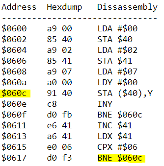
Many of the instructions for the 6502 have conditions that accessing certain memory locations will add to the cycle count for that operation. In the case of BNE, which we're using in this program, branching to the same page will incur a cost of 1 cycle while a branch to another page adds 2. Operations like this can be added to the "alt cycle" column, or vice versa, to keep track of control paths that deviate from the average when adding up our cycles. Where in memory we're branching to can be determined by taking a look at the disassembly on the emulator, at the top of the page. When we do we see that execution occurs exclusively on the first page of program data, so we'll just add the 1 cycle to our execution for BNE when adding that up.
With that in mind, let's get to the program itself, starting with a breakdown of the code.
LDA #$00    ; Load accumulator with value 00
STA $40     ; Store value of accumulator at $0040
LDA #$02    ; Load accumulator with value 02
STA $41     ; Store value of accumulator at $0041
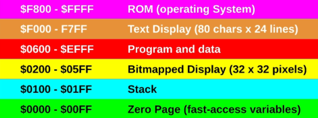
This block of code creates a pointer by storing the 2 byte address in the locations $0040 and $0041. When the processor puts the two bytes together it will get $0200 which is the location of the bmp display.
LDA #$07    ; Load accumulator with value 07 (colour yellow)

LDY #$00    ; Set the Y register, which is acting as the index
              in our loop, to 0

LOOP:
STA ($40),Y ; Store value of accumulator (yellow - $07) in
              address $0040 + Y (currently 0)

INY         ; Increment Y (index)

BNE LOOP    ; Return to LOOP statement and keep repeating
              until Y overflow occurs (end of page)

INC $41     ; Increment the value at address 41 (from page
              $0200 to $0300)
LDX $41     ; Load value of 41 to X register
CPX #$06    ; Compare value of X register (page number) to 06
BNE LOOP    ; Continue looping while Zero flag isn’t set
              (while prior comparison is false)
With the prior breakdown in mind, we can look at the cycle counts for each instruction and begin to get an idea of how long execution of our program should take.
Starting with the more straightforward instructions, we have the following count:
All of these instructions are performed a single time to set up the following loop, so getting their totals is just a matter of looking up their mnemonics and the type of address they're using for their operations.
The loop that follows after is performed for each memory location of each page of the display, so we get a cycle count of 1024 for each instruction save for the last, which branches 1020 times and doesn't branch on the last iteration of each loop, at which point execution progresses to the next block of code.
Finally, we have the end of the program which iterates the page number we're looping through. These instructions run 4 times (page $0200-$02FF, $0300-$03FF, $0400-$04FF and $0500-$05FF)
Summing our cycle count gives us the following:
We know:
- The given instructions will take 11327 cycles to execute
- 6502s can run at around 1 MHz
- We get the microseconds per clock cycle by calculating 1,000,000/(CPU Speed*1,000,000)
Thus the time is equal to the number of cycles * microseconds per clock, which comes out to 11327uS of execution time or 0.011327 seconds.

Posted on February 2, 2022
Join Our Newsletter. No Spam, Only the good stuff.
Sign up to receive the latest update from our blog.


