Vishnu Sivan
Posted on June 26, 2022

IoT framework aims at transforming everyday objects into intelligent systems by connecting the devices over the internet. Sensor networks, embedded systems, big data platforms, cloud computing and service-oriented architecture make up the ecosystem.
The NodeMCU is the abbreviation of Node MicroController Unit. It is an open-source development environment built on inexpensive SoC chips called the ESP8266. The ESP8266 is developed by Espressif Systems. It can be treated as a microcomputer and contains a CPU, RAM, WiFi module, operating system and SDK. It would be a great option for IoT projects.
In this article, we will learn about NodeMCU and will walk you through several sample projects using it.
Getting Started
Table of contents
- NodeMCU Pinout Diagram
- Setup the environment
- Arduino IDE installation
- Install dependencies and Configure the IDE
- First NodeMCU program
- Program 2: Blink an external LED
- Program 3: Remote LED control using a web server
Let’s begin with NodeMCU pinout diagram.
NodeMCU Pinout Diagram
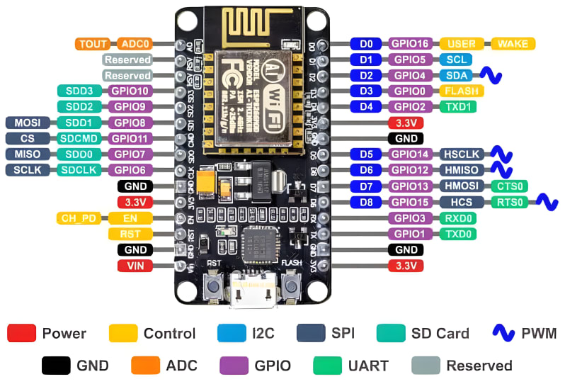
Download the Datasheet to know more about ESP8266.
Setup the environment
Arduino IDE installation
Arduino IDE is an open-source, Java-based development environment that is used to write, compile, and upload programs to the Arduino boards. It is available for download for Windows, Mac, and Linux.
-
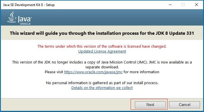
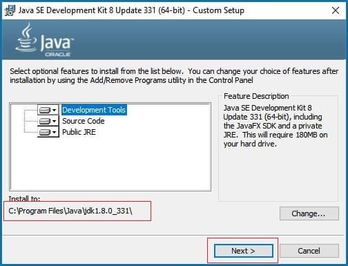
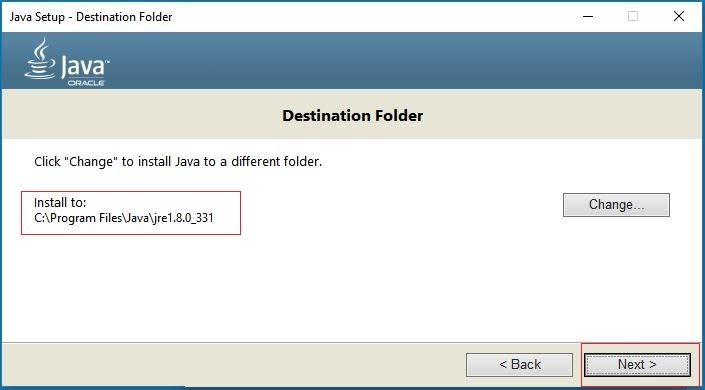
Download and install the Java JDK 1.8 or later
Add the Java JDK bin folder path in the environment variables
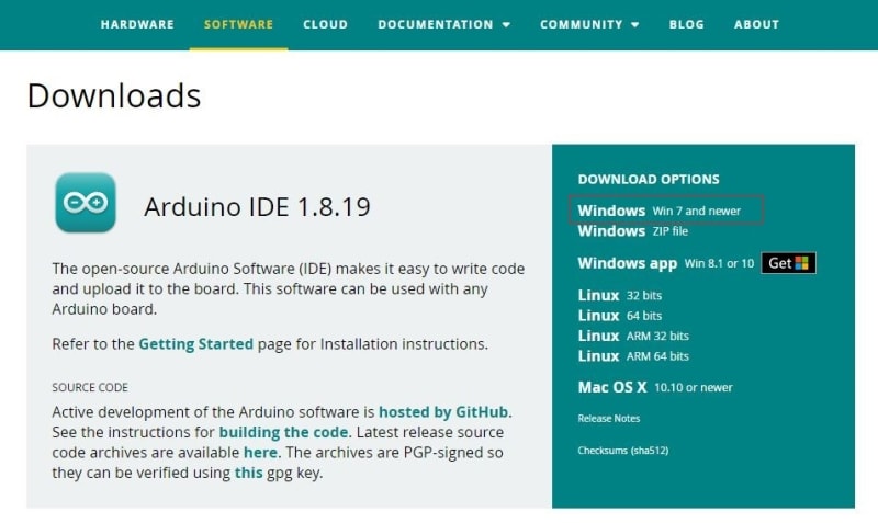
Download and install the Arduino IDE
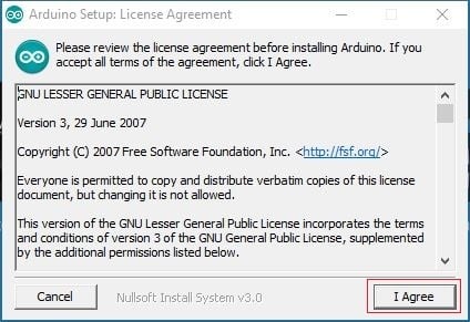
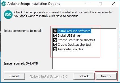
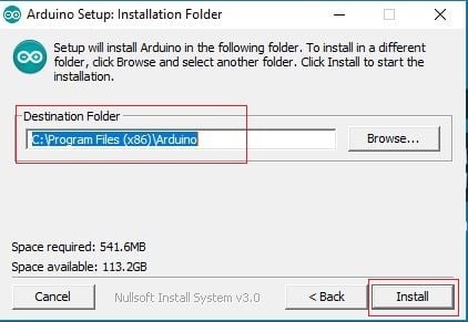
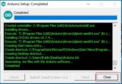
Double click on the installer and install the IDE with default configuration
Install dependencies and Configure the IDE
ESP8266 can be programmed just like a normal Arduino board. To do that, we must add a few additional packages to the Arduino IDE.
- Open the Arduino IDE. Select
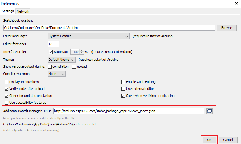
File -> Preferencesand insert the following URL in the Additional Boards Manager URLs input field.
http://arduino.esp8266.com/stable/package_esp8266com_index.json
- Select
Tools -> Board: [default board name] -> Boards Managerand search esp8266 in the search box of the newly opened window. Click on the Install button of the listed esp8266 by ESP8266 Community package.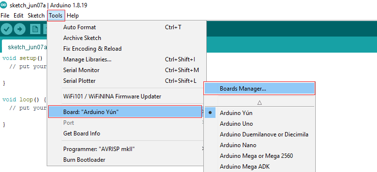
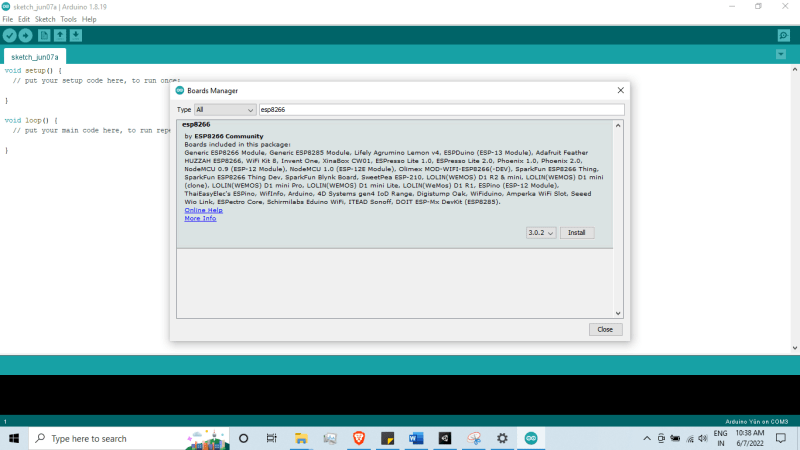
- Select Generic ESP8266 Module from the
Tools -> Board: [default board name] -> ESP8266 Boards (version)menu list.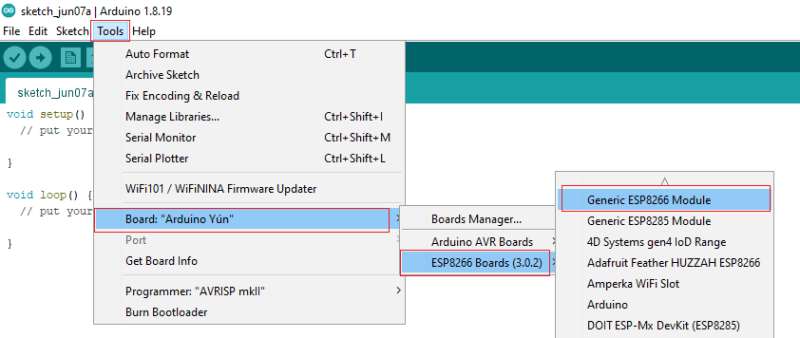
- Connect the NodeMCU board to the system via USB cable. Select the correct COM port from
Tools -> Portmenu.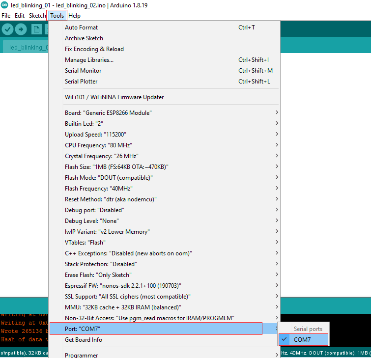
First NodeMCU program
Programs written in Arduino IDE are called sketches. A sketch is the unit of code that is uploaded to an Arduino board. These sketches are stored in files with the .ino extension.
Arduino Integrated Development Environment (IDE) v1 | Arduino Documentation
We will create a LED blinking program using the built-in LED on the NodeMCU board.
- Open the Arduino IDE and add the following code in the sketch window
int LED = 2;      // Assign LED to pin GPIO2
void setup() {
    // initialize GPIO2 as an output
    pinMode(LED, OUTPUT);
}
void loop() {
    digitalWrite(LED, LOW);     // turn the LED off
    delay(1000);                // wait for a second
    digitalWrite(LED, HIGH);    // turn the LED on
    delay(1000);
}
- Click on
File -> Saveto save the code - Click on the Verify icon to compile the code

- Click on the Upload button to burn the code on the NodeMCU module
 You will get a screenshot like the below after the successful code upload
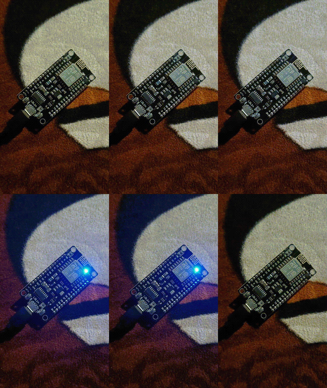
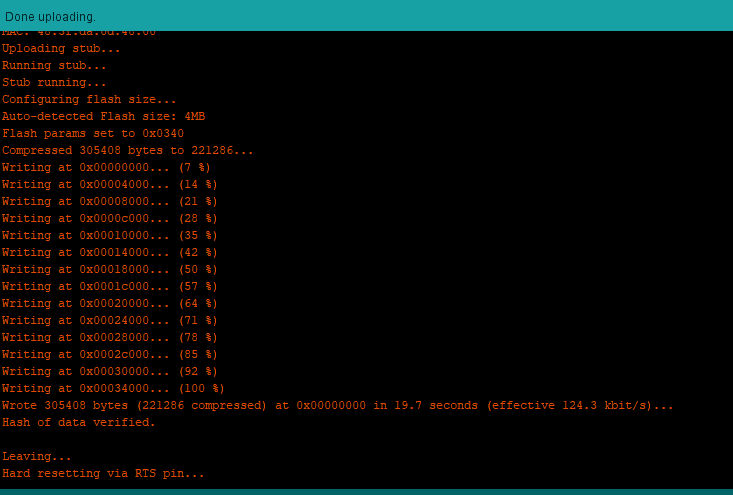 Now, you will see the built-in blue LED blink.
Program 2: Blink an external LED
We have programmed the built-in LED. Now, it’s time to try the same code on an external LED.
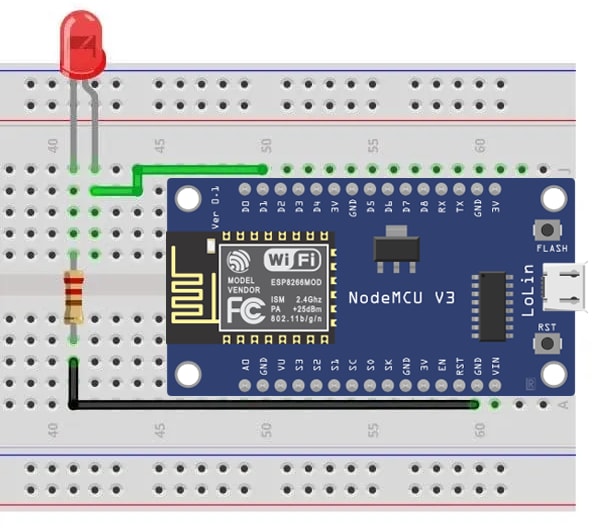
Follow the below diagram to connect the LED to the NodeMCU module. To do that, connect the LED on the D1 (GPIO 5) pin and a GND pin.
- Create a new sketch file from
File -> Newand add the following code to it.
int LED = 5; // Assign LED pin (D1 on NodeMCU)
void setup() {
    // initialize GPIO 5 as an output
    pinMode(LED, OUTPUT);
}
void loop() {
    digitalWrite(LED, HIGH);  // turn the LED on
    delay(1000);              // wait for a second
    digitalWrite(LED, LOW);   // turn the LED off
    delay(1000);              // wait for a second
}
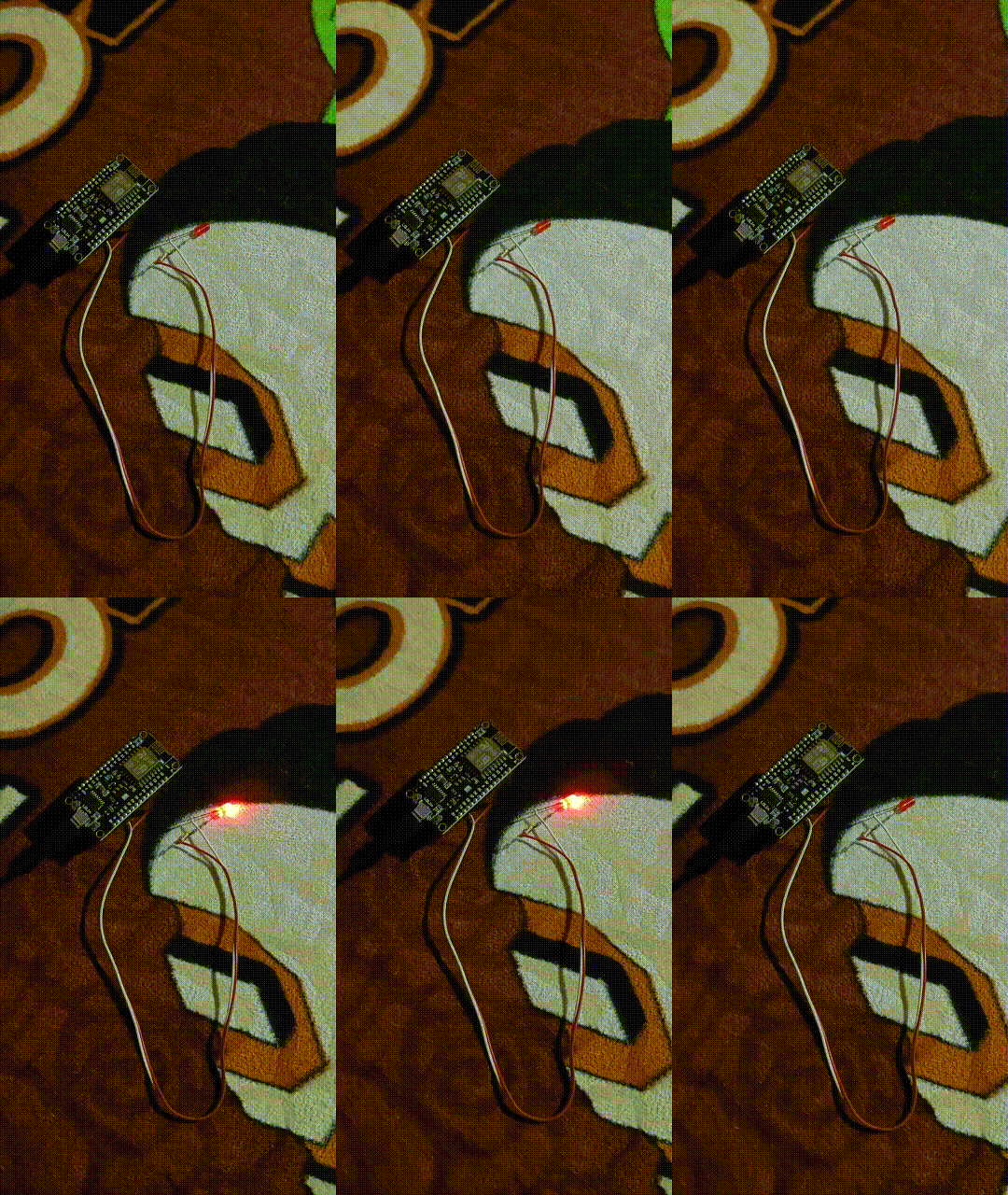
- To compile the code, click the Verify icon. Click the Upload button to upload the code to the NodeMCU. If the upload is successful, the output will look like as follows.
Program 3: Remote LED control using a web server
ESP8266 acts as a Web Server when connected to an existing WiFi network. It can be used to build web pages and use those sites to operate sensors. Additionally, we can view the sensor reading in real-time on the page.
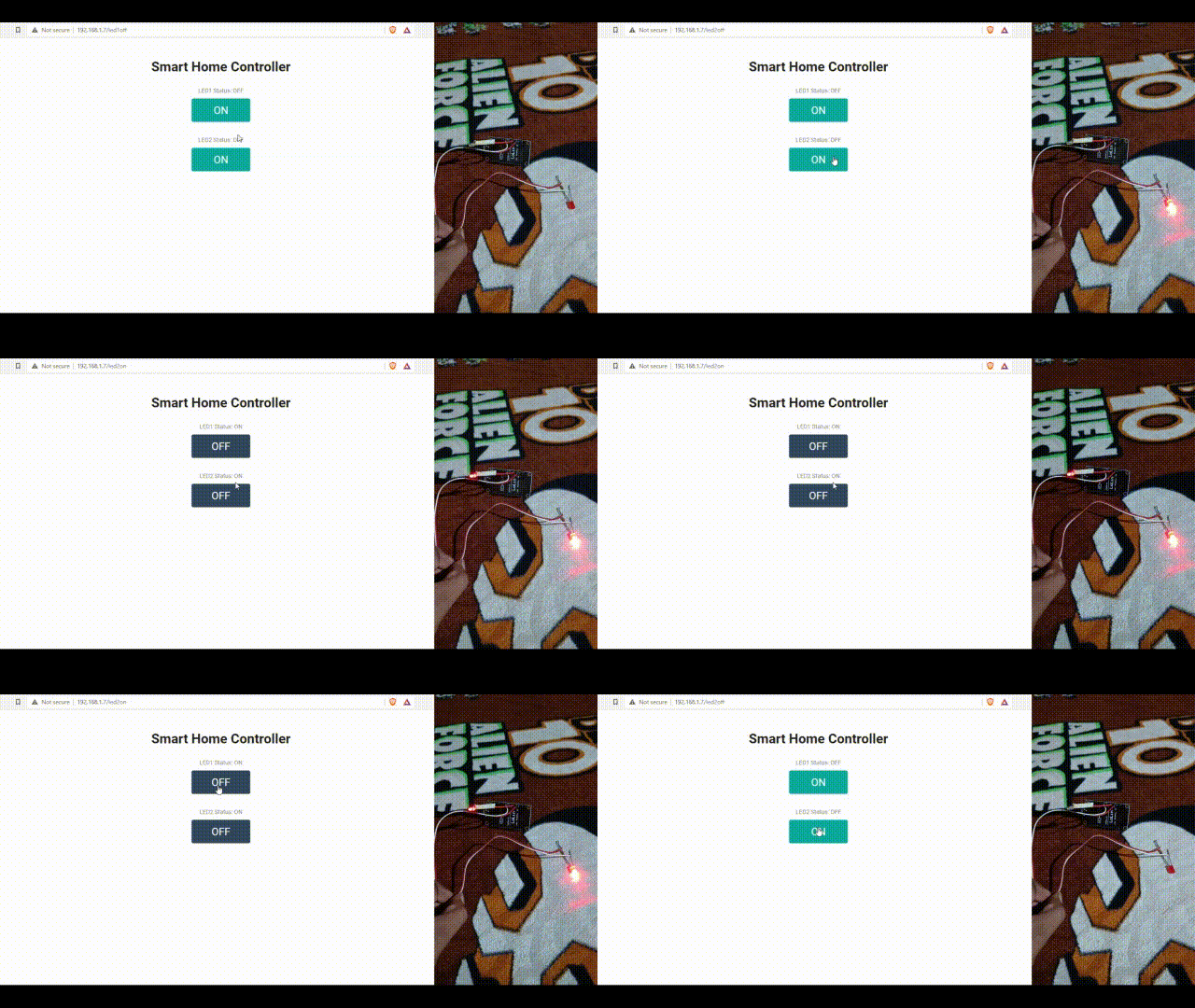
In this program, we will control two LED bulbs from a web page.
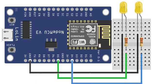
- Connect two LEDs to digital GPIO D5 and D4 through a 220Ω resistor like the illustration shown below.
- Create a new sketch file from
File -> Newand add the following code to it.
#include <ESP8266WiFi.h>
#include <ESP8266WebServer.h>
/* Put your SSID & Password */
const char* ssid = "YOUR_SSID";  // Enter SSID here
const char* password = "YOUR_WIFI_PASSWORD";  //Enter Password here
ESP8266WebServer server(80);
uint8_t LED1pin = 4;
bool LED1status = LOW;
uint8_t LED2pin = 5;
bool LED2status = LOW;
void setup() {
  WiFi.mode(WIFI_STA);
  WiFi.begin(ssid, password);

  Serial.begin(115200);
  pinMode(LED1pin, OUTPUT);
  pinMode(LED2pin, OUTPUT);
  delay(100);
while (WiFi.status() != WL_CONNECTED) {
    delay(200);
    Serial.print(".");
  }
Serial.println("");
  Serial.print("Connected to ");
  Serial.println(ssid);
  Serial.print("IP address: ");
  Serial.println(WiFi.localIP());

  server.on("/", handle_OnConnect);
  server.on("/led1on", handle_led1on);
  server.on("/led1off", handle_led1off);
  server.on("/led2on", handle_led2on);
  server.on("/led2off", handle_led2off);
  server.onNotFound(handle_NotFound);

  server.begin();
  Serial.println("HTTP server started");
}
void loop() {
  server.handleClient();
  if(LED1status)
    digitalWrite(LED1pin, HIGH);
  else
    digitalWrite(LED1pin, LOW);

  if(LED2status)
    digitalWrite(LED2pin, HIGH);
  else
    digitalWrite(LED2pin, LOW);
}
void handle_OnConnect() {
  LED1status = LOW;
  LED2status = LOW;
  Serial.println("GPIO2 Status: OFF | GPIO4 Status: OFF");
  server.send(200, "text/html", SendHTML(LED1status,LED2status));
}
void handle_led1on() {
  LED1status = HIGH;
  Serial.println("GPIO4 Status: ON");
  server.send(200, "text/html", SendHTML(true,LED2status));
}
void handle_led1off() {
  LED1status = LOW;
  Serial.println("GPIO4 Status: OFF");
  server.send(200, "text/html", SendHTML(false,LED2status));
}
void handle_led2on() {
  LED2status = HIGH;
  Serial.println("GPIO2 Status: ON");
  server.send(200, "text/html", SendHTML(LED1status,true));
}
void handle_led2off() {
  LED2status = LOW;
  Serial.println("GPIO2 Status: OFF");
  server.send(200, "text/html", SendHTML(LED1status,false));
}
void handle_NotFound(){
  server.send(404, "text/plain", "Not found");
}
String SendHTML(uint8_t led1stat,uint8_t led2stat){
  String ptr = "<!DOCTYPE html> <html>\n";
  ptr +="<head><meta name=\"viewport\" content=\"width=device-width, initial-scale=1.0, user-scalable=no\">\n";
  ptr +="<title>LED Control</title>\n";
  ptr +="<style>html { font-family: Roboto; display: inline-block; margin: 0px auto; text-align: center;}\n";
  ptr +="body{margin-top: 50px;} h1 {color: #222222;margin: 50px auto 30px;} h3 {color: #444444;margin-bottom: 50px;}\n";
  ptr +=".button {display: block;width: 80px;background-color: #1abc1a;border: none;color: white;padding: 13px 30px;text-decoration: none;font-size: 25px;margin: 0px auto 35px;cursor: pointer;border-radius: 4px;}\n";
  ptr +=".button-on {background-color: #1abc9c;}\n";
  ptr +=".button-on:active {background-color: #16a085;}\n";
  ptr +=".button-off {background-color: #34495e;}\n";
  ptr +=".button-off:active {background-color: #2c3e50;}\n";
  ptr +="p {font-size: 14px;color: #888;margin-bottom: 10px;}\n";
  ptr +="</style>\n";
  ptr +="</head>\n";
  ptr +="<body>\n";
  ptr +="<h1>Smart Home Controller</h1>\n";

  if(led1stat)
    ptr +="<p>LED1 Status: ON</p><a class=\"button button-off\" href=\"/led1off\">OFF</a>\n";
  else
    ptr +="<p>LED1 Status: OFF</p><a class=\"button button-on\" href=\"/led1on\">ON</a>\n";
if(led2stat)
    ptr +="<p>LED2 Status: ON</p><a class=\"button button-off\" href=\"/led2off\">OFF</a>\n";
  else
    ptr +="<p>LED2 Status: OFF</p><a class=\"button button-on\" href=\"/led2on\">ON</a>\n";
ptr +="</body>\n";
  ptr +="</html>\n";
  return ptr;
}
- Click on the Verify icon to compile the code then click on the Upload button to upload the code on the NodeMCU. If the upload is successful then we can see the output as follows.
Thanks for reading this article.
To get the article in pdf format: Start your IoT journey with NodeMCU
The full source code of the programs is available on
GitHub - codemaker2015/ESP2866-NodeMCU-examples
The article is also available on Medium
If you enjoyed this article, please click on the heart button ♥ and share to help others find it!

Posted on June 26, 2022
Join Our Newsletter. No Spam, Only the good stuff.
Sign up to receive the latest update from our blog.

