InterSystems IRIS Example Reference Architectures for Amazon Web Services (AWS)

InterSystems Developer
Posted on September 27, 2020
The Amazon Web Services (AWS) Cloud provides a broad set of infrastructure services, such as compute resources, storage options, and networking that are delivered as a utility: on-demand, available in seconds, with pay-as-you-go pricing. New services can be provisioned quickly, without upfront capital expense. This allows enterprises, start-ups, small and medium-sized businesses, and customers in the public sector to access the building blocks they need to respond quickly to changing business requirements.
Updated: 15-Oct, 2019
The following overview and details are provided by Amazon and can be found here.
Overview
AWS Global Infrastructure
The AWS Cloud infrastructure is built around Regions and Availability Zones (AZs). A Region is a physical location in the world where we have multiple AZs. AZs consist of one or more discrete data centers, each with redundant power, networking, and connectivity, housed in separate facilities. These AZs offer you the ability to operate production applications and databases that are more highly available, fault tolerant, and scalable than would be possible from a single data center.
Details of AWS Global Infrastructure can be found here.
AWS Security and Compliance
Security in the cloud is much like security in your on-premises data centers—only without the costs of maintaining facilities and hardware. In the cloud, you don’t have to manage physical servers or storage devices. Instead, you use software-based security tools to monitor and protect the flow of information into and of out of your cloud resources.
The AWS Cloud enables a shared responsibility model. While AWS manages security of the cloud, you are responsible for security in the cloud. This means that you retain control of the security you choose to implement to protect your own content, platform, applications, systems, and networks no differently than you would in an on-site data center.
Details of AWS Cloud Security can be found here.
The IT infrastructure that AWS provides to its customers is designed and managed in alignment with best security practices and a variety of IT security standards. A complete list of assurance programs with which AWS complies with can be found here.
AWS Cloud Platform
AWS consists of many cloud services that you can use in combinations tailored to your business or organizational needs. The following sub-section introduces the major AWS services by category that are commonly used with InterSystems IRIS deployments. There are many other services available and potentially useful for your specific application. Be sure to research those as needed.
To access the services, you can use the AWS Management Console, the Command Line Interface, or Software Development Kits (SDKs).
| Component | Details |
|---|---|
| AWS Management Console | Details of the AWS Management Console can be found here. |
| AWS Command-line interface | Details of the AWS Command Line Interface (CLI) can be found here. |
| AWS Software Development Kits (SDK) | Details of AWS Software Development Kits (SDK) can be found here. |
| AWS Compute | There are numerous options available: Details of Amazon Elastic Cloud Computing (EC2) can be found here Details of Amazon EC2 Container Service (ECS) can be found here Details of Amazon EC2 Container Registry (ECR) can be found here Details of Amazon Auto Scaling can be found here |
| AWS Storage | There are numerous options available: Details of Amazon Elastic Block Store (EBS) can be found here Details of Amazon Simple Storage Service (S3) can be found here Details of Amazon Elastic File System (EFS) can be found here |
| AWS Networking | There are numerous options available. Details of Amazon Virtual Private Cloud (VPC) can be found here Details of Amazon Elastic IP Addresses can be found here Details of Amazon Elastic Network Interfaces can be found here Details of Amazon Enhanced Networking for Linux can be found here Details of Amazon Elastic Load Balancing (ELB) can be found here Details of Amazon Route 53 can be found here |
InterSystems IRIS Sample Architectures
As part of this article, sample InterSystems IRIS deployments for AWS are provided as a starting point for your application specific deployment. These can be used as a guideline for numerous deployment possibilities. This reference architecture demonstrates highly robust deployment options starting with the smallest deployments to massively scalable workloads for both compute and data requirements.
High availability and disaster recovery options are covered in this document along with other recommended system operations. It is expected these will be modified by the individual to support their organization’s standard practices and security policies.
InterSystems is available for further discussions or questions of AWS-based InterSystems IRIS deployments for your specific application.
Sample Reference Architectures
The following sample architectures will provide several different configurations with increasing capacity and capabilities. Consider these examples of small development / production / large production / production with sharded cluster that show the progression from starting with a small modest configuration for development efforts and then growing to massively scalable solutions with proper high availability across zones and multi-region disaster recovery. In addition, an example architecture of using the new sharding capabilities of InterSystems IRIS Data Platform for hybrid workloads with massively parallel SQL query processing.
Small Development Configuration
In this example, a minimal configuration is used to illustrates a small development environment capable of supporting up to 10 developers and 100GB of data. More developers and stored data can easily be supported by simply changing the virtual machine instance type and increasing storage of the EBS volume(s) as appropriate.
This is adequate to support development efforts and become familiar with InterSystems IRIS functionality along with Docker container building and orchestration if desired. High availability with database mirroring is typically not used with a small configuration, however it can be added at any time if high availability is needed.
Small Configuration Sample Diagram
The below sample diagram in Figure 2.1.1-a illustrates the table of resources in Figure 2.1.1-b. The gateways included are just examples, and can be adjusted accordingly to suit your organization’s standard network practices.
Figure-2.1.1-a: Sample Small Development Architecture
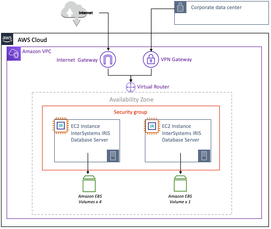
The following resources within the AWS VPC are provisioned as a minimum small configuration. AWS resources can be added or removed as required.
Small Configuration AWS Resources
Sample of Small Configuration AWS resources is provided below in the following table.
Figure 2.1.1-b: Sample table of Small Configuration AWS Resources
Proper network security and firewall rules need to be considered to prevent unwanted access into the VPC. Amazon provides network security best practices for getting started which can be found here:
https://docs.aws.amazon.com/vpc/index.html#lang/en_us
https://docs.aws.amazon.com/quickstart/latest/vpc/architecture.html#best-practices
Note: VM instances require a public IP address to reach AWS services. While this practice might raise some concerns, AWS recommends limiting the incoming traffic to these VM instances by using firewall rules.
If your security policy requires truly internal VM instances, you will need to set up a NAT proxy manually on your network and a corresponding route so that the internal instances can reach the Internet. It is important to note that you cannot connect to a fully internal VM instance directly by using SSH. To connect to such internal machines, you must set up a bastion instance that has an external IP address and then tunnel through it. A bastion Host can be provisioned to provide the external facing point of entry into your VPC.
Details of using a bastion hosts can he found here:
https://aws.amazon.com/blogs/security/controlling-network-access-to-ec2-instances-using-a-bastion-server/
https://docs.aws.amazon.com/quickstart/latest/linux-bastion/architecture.html
Production Configuration
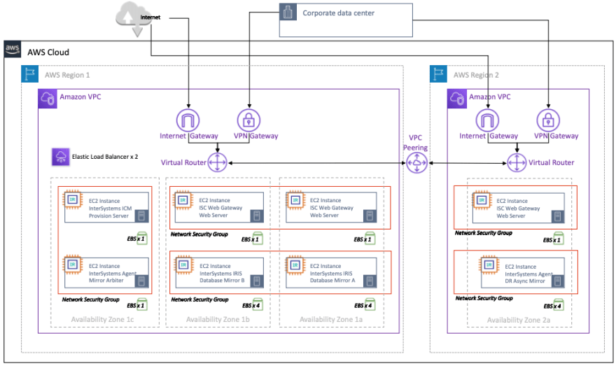
In this example, a more sizable configuration as an example production configuration that incorporates InterSystems IRIS database mirroring capability to support high availability and disaster recovery.
Included in this configuration is a synchronous mirror pair of InterSystems IRIS database servers split between two availability zones within region-1 for automatic failover, and a third DR asynchronous mirror member in region-2 for disaster recovery in the unlikely event an entire AWS region is offline.
Details of a multiple Region with Multi-VPC Connectivity can be found here.
The InterSystems Arbiter and ICM server deployed in a separate third zone for added resiliency. The sample architecture also includes a set of optional load balanced web servers to support a web-enabled application. These web servers with the InterSystems Gateway can be scaled independently as needed.
Production Configuration Sample Diagram
The sample diagram in Figure 2.2.1-a illustrates the table of resources in Figure 2.2.1-b. The gateways included are just examples, and can be adjusted accordingly to suit your organization’s standard network practices.
Figure 2.2.1-a: Sample Production Architecture with High Availability and Disaster Recovery
The following resources within the AWS VPC are recommended as a minimum to support a production workload for a web application. AWS resources can be added or removed as required.
Production Configuration AWS Resources
Sample of Production Configuration AWS resources is provided below in the following table.
Figure 2.2.1-b: Table of Production Configuration AWS Resources
Figure 2.2.1-b: Table of Production Configuration AWS Resources (continued)
Large Production Configuration
In this example, a massively scaled configuration is provided by expanding on the InterSystems IRIS capability to also introduce application servers using InterSystems’ Enterprise Cache Protocol (ECP) to provide massive horizontal scaling of users. An even higher level of availability is included in this example because of ECP clients preserving session details even in the event of a database instance failover. Multiple AWS availability zones are used with both ECP-based application servers and database mirror members deployed in multiple regions. This configuration is capable of supporting tens of millions database accesses per second and multiple terabytes of data.
Production Configuration Sample Diagram
The sample diagram in Figure 2.3.1-a illustrates the table of resources in Figure 2.3.1-b. The gateways included are just examples, and can be adjusted accordingly to suit your organization’s standard network practices.
Included in this configuration is a failover mirror pair, four or more ECP clients (application servers), and one or more web servers per application server. The failover database mirror pairs are split between two different AWS availability zones in the same region for fault domain protection with the InterSystems Arbiter and ICM server deployed in a separate third zone for added resiliency.
Disaster recovery extends to a second AWS region and availability zone(s) similar to the earlier example. Multiple DR regions can be used with multiple DR Async mirror member targets if desired.
Figure 2.3.1-a: Sample Large Production Architecture with ECP Application Servers

The following resources within the AWS VPC Project are recommended as a minimum recommendation to support a sharded cluster. AWS resources can be added or removed as required.
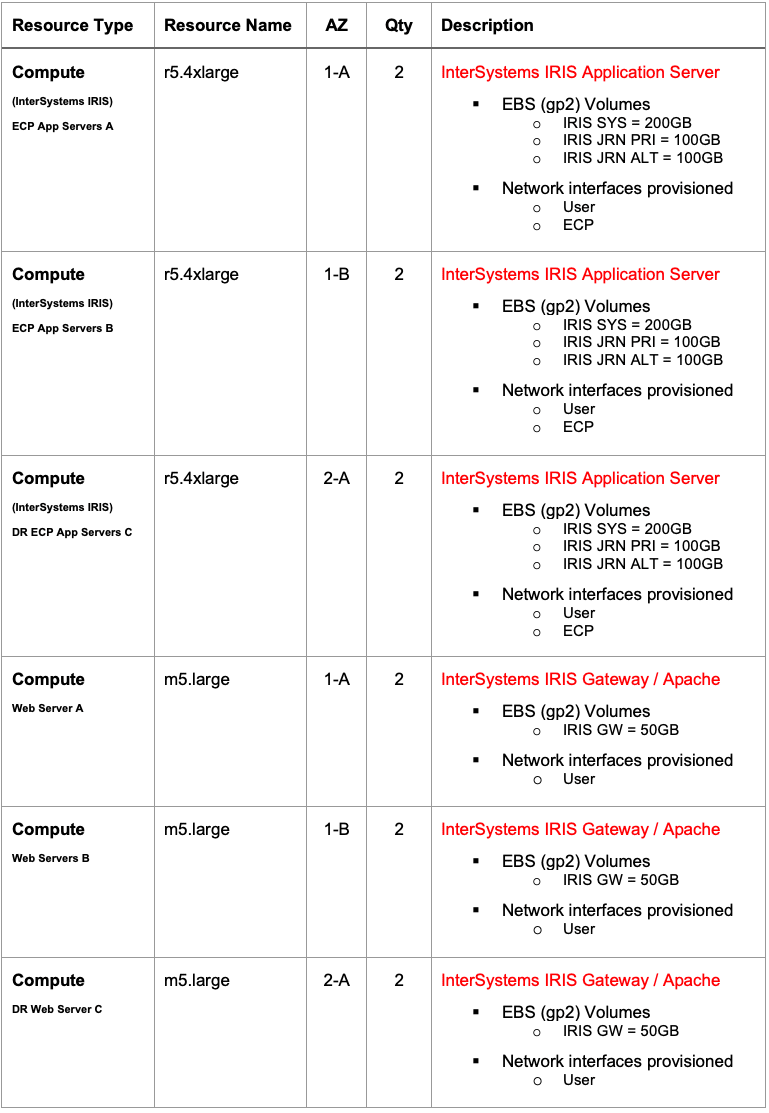
Large Production Configuration AWS Resources
Sample of Large Production Configuration AWS resources is provided below in the following table.
Figure 2.3.1-b: Table of Large Configuration with ECP Application Servers AWS Resources
Figure 2.3.1-b: Table of Large Configuration with ECP Application Servers AWS Resources (continued)
Figure 2.3.1-b: Table of Large Configuration with ECP Application Servers AWS Resources (continued)
Production Configuration with InterSystems IRIS Sharded Cluster
In this example, a horizontally scaled configuration for hybrid workloads with SQL is provided by including the new sharded cluster capabilities of InterSystems IRIS to provide massive horizontal scaling of SQL queries and tables across multiple systems. Details of InterSystems IRIS sharded cluster and its capabilities are discussed further in section 9 of this article.
Production with Sharded Cluster Configuration Sample Diagram
The sample diagram in Figure 2.4.1-a illustrates the table of resources in Figure 2.4.1-b. The gateways included are just examples, and can be adjusted accordingly to suit your organization’s standard network practices.
Included in this configuration are four mirror pairs as the data nodes. Each of the failover database mirror pairs are split between two different AWS availability zones in the same region for fault domain protection with the InterSystems Arbiter and ICM server deployed in a separate third zone for added resiliency.
This configuration allows for all the database access methods to be available from any data node in the cluster. The large SQL table(s) data is physically partitioned across all data nodes to allow for massive parallelization of both query processing and data volume. Combining all these capabilities provides the ability to support complex hybrid workloads such as large-scale analytical SQL querying with concurrent ingestion of new data, all within a single InterSystems IRIS Data Platform.
Figure 2.4.1-a: Sample Production Configuration with Sharded Cluster with High Availability
Note that in the above diagram and the “resource type” column in the table below, the term “EC2” is an AWS term representing an AWS virtual server instance as described further in section 3.1 of this document. It does not represent or imply the use of “compute nodes” in the cluster architecture described in chapter 9.
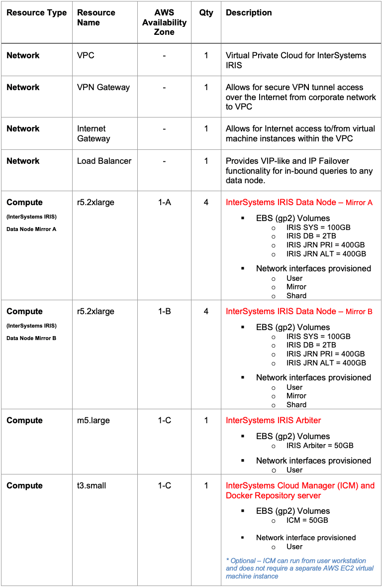
The following resources within the AWS VPC are recommended as a minimum recommendation to support a sharded cluster. AWS resources can be added or removed as required.
Production with Sharded Cluster Configuration AWS Resources
Sample of Production with Sharded Cluster Configuration AWS resources is provided below in the following table.
Figure 2.4.1-b: Table of Sample Production Configuration with Sharded Cluster AWS Resources
Introduction to Cloud Concepts
Amazon Web Services (AWS) provides a feature rich cloud environment for Infrastructure-as-a-Service (IaaS) fully capable of supporting all of InterSystems products including support for container-based DevOps with the new InterSystems IRIS Data Platform. Care must be taken, as with any platform or deployment model, to ensure all aspects of an environment are considered such as performance, availability, system operations, high availability, disaster recovery, security controls, and other management procedures. This article will cover the three major components of all cloud deployments: Compute, Storage, and Networking.
Compute Engines (Virtual Machines)
Within AWS EC2 there are several options available for compute engine resources with numerous virtual CPU and memory specifications and associated storage options. One item to note within AWS EC2, references to the number of vCPUs in a given machine type equates to one vCPU is one hyper-thread on the physical host at the hypervisor layer.
For the purposes of this document m5* and r5* EC2 instance types will be used and are most widely available in most AWS deployment regions. However, the use of other specialized instance types such as: x1* with very large memory are great options for very large working datasets keeping massive amounts of data cached in memory, or i3* with NVMe local instance storage. Details of the AWS Service Level Agreement (SLA) can be found here.
Disk Storage
The storage type most directly related to InterSystems products are the persistent disk types, however local storage may be used for high levels of performance if data availability restrictions are understood and accommodated. There are several other options such as S3 (buckets) and Elastic File Store (EFS), however those are more specific to an individual application’s requirements rather than supporting the operation of InterSystems IRIS Data Platform.
Like most other cloud providers, AWS imposes limitations on the amount of persistent storage that can be associated to an individual compute engine. These limits include the maximum size of each disk, the number of persistent disks attached to each compute engine, and the amount of IOPS per persistent disk with an overall individual compute engine instance IOPS cap. In addition, there are imposed IOPS limits per GB of disk space, so at times provisioning more disk capacity is required to achieve desired IOPS rate.
These limits may change over time and to be confirmed with AWS as appropriate.
There are three types of persistent storage types for disk volumes: EBS gp2 (SSD), EBS st1 (HDD), and EBS io1 (SSD). The standard EBS gp2 disks are more suited for production workloads that require predictable low-latency IOPS and higher throughput. Standard Persistent disks are more an economical option for non-production development and test or archive type workloads.
Details of the various disk types and limitations can be found here.
VPC Networking
The virtual private cloud (VPC) network is highly recommended to support the various components of InterSystems IRIS Data Platform along with providing proper network security controls, various gateways, routing, internal IP address assignments, network interface isolation, and access controls. An example VPC will be detailed in the examples provided within this document.
Details of VPC networking and firewalls can be found here.
Virtual Private Cloud (VPC) Overview
Details of AWS VPC are provided here.
In most large cloud deployments, multiple VPCs are provisioned to isolate the various gateways types from application-centric VPCs and leverage VPC peering for inbound and outbound communications. It is highly recommended to consult with your network administrator for details on allowable subnets and any organizational firewall rules of your company. VPC peering is not covered in this document.
In the examples provided in this document, a single VPC with three subnets will be used to provide network isolation of the various components for predictable latency and bandwidth and security isolation of the various InterSystems IRIS components.
Network Gateway and Subnet Definitions
Two gateways are provided in the example in this document to support both Internet and secure VPN connectivity. Each ingress access is required to have appropriate firewall and routing rules to provide adequate security for the application. Details on how to use VPC Route Tables can be found here.
Three subnets are used in the provided example architectures dedicated for use with InterSystems IRIS Data Platform. The use of these separate network subnets and network interfaces allows for flexibility in security controls and bandwidth protection and monitoring for each of the three above major components. Details for creating virtual machine instances with multiple network interfaces can be found here.
The subnets included in these examples:
- User Space Network for Inbound connected users and queries
- Shard Network for Inter-shard communications between the shard nodes
- Mirroring Network for high availability using synchronous replication and automatic failover of individual data nodes.
Note: Failover synchronous database mirroring is only recommended between multiple zones which have low latency interconnects within a single AWS region. Latency between regions is typically too high for to provide a positive user experience especially for deployment with a high rate of updates.
Internal Load Balancers
Most IaaS cloud providers lack the ability to provide for a Virtual IP (VIP) address that is typically used in automatic database failover designs. To address this, several of the most commonly used connectivity methods, specifically ECP clients and Web Gateways, are enhanced within InterSystems IRIS to no longer rely on VIP capabilities making them mirror-aware and automatic.
Connectivity methods such as xDBC, direct TCP/IP sockets, or other direct connect protocols, require the use of a VIP-like address. To support those inbound protocols, InterSystems database mirroring technology makes it possible to provide automatic failover for those connectivity methods within AWS using a health check status page called mirror_status.cxw to interact with the load balancer to achieve VIP-like functionality of the load balancer only directing traffic to the active primary mirror member, thus providing a complete and robust high availability design within AWS.
Details of AWS Elastic Load Balancer (ELB) can be found here.
Figure 4.2-a: Automatic Failover without a Virtual IP Address
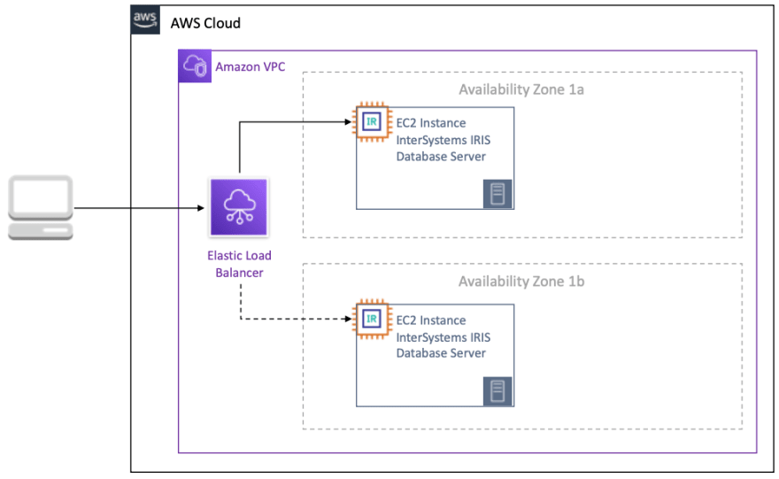
Details of using a load balancer to provide VIP-like functionality is provided here.
Sample VPC Topology
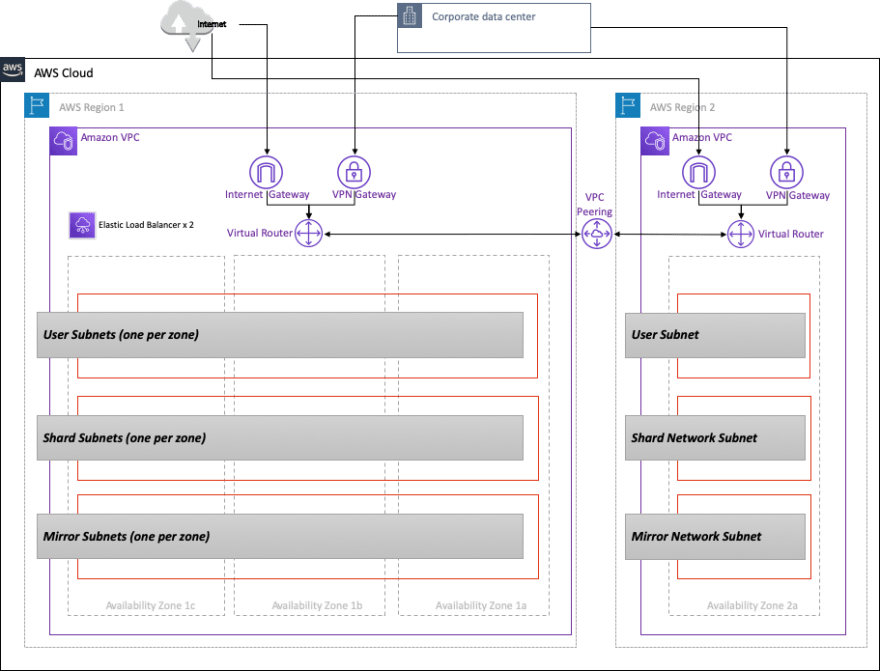
Combining all the components together, the following illustration in Figure 4.3-a demonstrates the layout of a VPC with the following characteristics:
- Leverages multiple zones within a region for high availability
- Provides two regions for disaster recovery
- Utilizes multiple subnets for network segregation
- Includes separate gateways for VPC Peering, Internet, and VPN connectivity
- Uses cloud load balancer for IP failover for mirror members Please note in AWS each subnet must reside entirely within one availability zone and cannot span zones. So, in the example below, network security or routing rules need to be properly defined. Details on AWS VPC subnets can be found here.
Figure 4.3-a: Example VPC Network Topology
Persistent Storage Overview
As discussed in the introduction, the use of AWS Elastic Block Store (EBS) Volumes is recommended and specifically EBS gp2 volume types. EBS gp2 volumes are recommended due to the higher read and write IOPS rates and low latency required for transactional and analytical database workloads. Local SSDs may be used in certain circumstances, however beware that the performance gains of local SSDs comes with certain trade-offs in availability, durability, and flexibility.
Details of Local SSD data persistence can be found here to understand the events of when Local SSD data is preserved and when not.
LVM PE Striping
Like other cloud providers, AWS imposes numerous limits on storage both in IOPS, space capacity, and number of devices per virtual machine instance. Consult AWS documentation for current limits which can be found here.
With these limits, LVM striping becomes necessary to maximize IOPS beyond that of a single disk device for a database instance. In the example virtual machine instances provided, the following disk layouts are recommended. Performance limits associated with SSD persistent disks can be found here.
Note: There is currently a maximum of 40 EBS volumes per Linux EC2 instance although AWS resource capabilities change often so please consult with AWS documentation for current limitations.
Figure 5.1-a: Example LVM Volume Group Allocation
The benefits of LVM striping allows for spreading out random IO workloads to more disk devices and inherit disk queues. Below is an example of how to use LVM striping with Linux for the database volume group. This example will use four disks in an LVM PE stripe with a physical extent (PE) size of 4MB. Alternatively, larger PE sizes can be used if needed.
Step 1: Create Standard or SSD Persistent Disks as needed
Step 2: IO scheduler is NOOP for each of the disk devices using “lsblk -do NAME,SCHED”
Step 3: Identify disk devices using “lsblk -do KNAME,TYPE,SIZE,MODEL”
Step 4: Create Volume Group with new disk devices
vgcreate s 4M <vg name> <list of all disks just created>- example: vgcreate -s 4M vg_iris_db /dev/sd[h-k]
Step 4: Create Logical Volume
lvcreate n <lv name> -L <size of LV> -i <number of disks in volume group> -I 4MB <vg name>-
example:
lvcreate -n lv_irisdb01 -L 1000G -i 4 -I 4M vg_iris_db
Step 5: Create File System
mkfs.xfs K <logical volume device>-
example:
mkfs.xfs -K /dev/vg_iris_db/lv_irisdb01
Step 6: Mount File System
-
edit /etc/fstab with following mount entries/dev/mapper/vg_iris_db-lv_irisdb01 /vol-iris/db xfs defaults 0 0-
mount /vol-iris/dbUsing the above table, each of the InterSystems IRIS servers will have the following configuration with two disks for SYS, four disks for DB, two disks for primary journals and two disks for alternate journals.
Figure 5.1-b: InterSystems IRIS LVM Configuration
For growth LVM allows for expanding devices and logical volumes when needed without interruption. Consult with Linux documentation on best practices for ongoing management and expansion of LVM volumes.
Note: The enablement of asynchronous IO for both the database and the write image journal files are highly recommend. See the community article for details on enabling on Linux.
Provisioning
New with InterSystems IRIS is InterSystems Cloud Manager (ICM). ICM carries out many tasks and offers many options for provisioning InterSystems IRIS Data Platform. ICM is provided as a Docker image that includes everything for provisioning a robust AWS cloud-based solution.
ICM currently support provisioning on the following platforms:
- Amazon Web Services including GovCloud (AWS / GovCloud)
- Google Cloud Platform (GCP)
- Microsoft Azure Resource Manager including Government (ARM / MAG)
- VMware vSphere (ESXi) ICM and Docker can run from either a desktop/laptop workstation or have a centralized dedicated modest “provisioning” server and centralized repository.
The role of ICM in the application lifecycle is Define -> Provision -> Deploy -> Manage
Details for installing and using ICM with Docker can be found here.
NOTE: The use of ICM is not required for any cloud deployment. The traditional method of installation and deployment with tar-ball distributions is fully supported and available. However, ICM is recommended for ease of provisioning and management in cloud deployments.
Container Monitoring
ICM includes two basic monitoring facilities for container-based deployments: Rancherand Weave Scope. Neither are deployed by default, and need to be specified in the defaults file using the Monitorfield. Details for monitoring, orchestration, and scheduling with ICM can be found here.
An overview of Rancher and documentation can be found here.
An overview of Weave Scope and documentation can be found here.
High Availability
InterSystems database mirroring provides the highest level of availability in any cloud environment. AWS does not provide any availability guarantees for a single EC2 instance, so database mirroring is required database tier which can also be coupled with load balancing and auto-scale groups.
Earlier sections discussed how a cloud load balancer will provide automatic IP address failover for a Virtual IP (VIP-like) capability with database mirroring. The cloud load balancer uses the mirror_status.cxwhealth check status page mentioned earlier in the Internal Load Balancerssection. There are two modes of database mirroring - synchronous with automatic failover and asynchronous mirroring. In this example, synchronous failover mirroring will be covered. The details of mirroring can he found here.
The most basic mirroring configuration is a pair of failover mirror members in an arbiter-controlled configuration. The arbiter is placed in a third zone within the same region to protect from potential availability zone outages impacting both the arbiter and one of the mirror members.
There are many ways mirroring can be setup specifically in the network configuration. In this example, we will use the network subnets defined previously in the Network Gateway and Subnet Definitions section of this document. Example IP address schemes will be provided in a following section and for the purpose of this section, only the network interfaces and designated subnets will be depicted.
Figure 7-a: Sample mirror configuration with arbiter
Disaster Recovery
InterSystems database mirroring extends the capability of high available to also support disaster recovery to another AWS geographic region to support operational resiliency in the unlikely event of an entire AWS region going offline. How an application is to endure such outages depends on the recovery time objective (RTO) and recovery point objectives (RPO). These will provide the initial framework for the analysis required to design a proper disaster recovery plan. The following link provides a guide for the items to be considered when developing a disaster recovery plan for your application. https://aws.amazon.com/disaster-recovery/
Asynchronous Database Mirroring
InterSystems IRIS Data Platform’s database mirroring provides robust capabilities for asynchronously replicating data between AWS availability zones and regions to help support the RTO and RPO goals of your disaster recovery plan. Details of async mirror members can be found here.
Similar to the earlier high availability section, a cloud load balancer will provide automatic IP address failover for a Virtual IP (VIP-like) capability for DR asynchronous mirroring as well using the same mirror_status.cxw health check status page mentioned earlier in the Internal Load Balancers section.
In this example, DR asynchronous failover mirroring will be covered along with the introduction of the AWS Route53 DNS service to provide upstream systems and client workstations with a single DNS address regardless of which availability zone or region your InterSystems IRIS deployment is operating.
Details of AWS Route53 can be found here.
Figure 8.1-a: Sample DR Asynchronous Mirroring with AWS Route53

In the above example, the IP addresses of both region’s Elastic Load Balancer (ELB) that front-end the InterSystems IRIS instances are provided Route53, and it will only direct traffic to whichever mirror member is the active primary mirror regardless of the availability zone or region it is located.
Sharded Cluster
InterSystems IRIS includes a comprehensive set of capabilities to scale your applications, which can be applied alone or in combination, depending on the nature of your workload and the specific performance challenges it faces. One of these, sharding, partitions both data and its associated cache across a number of servers, providing flexible, inexpensive performance scaling for queries and data ingestion while maximizing infrastructure value through highly efficient resource utilization. An InterSystems IRIS sharded cluster can provide significant performance benefits for a wide variety of applications, but especially for those with workloads that include one or more of the following:
- High-volume or high-speed data ingestion, or a combination.
- Relatively large data sets, queries that return large amounts of data, or both.
- Complex queries that do large amounts of data processing, such as those that scan a lot of data on disk or involve significant compute work.
Each of these factors on its own influences the potential gain from sharding, but the benefit may be enhanced where they combine. For example, a combination of all three factors — large amounts of data ingested quickly, large data sets, and complex queries that retrieve and process a lot of data — makes many of today’s analytic workloads very good candidates for sharding.
Note that these characteristics all have to do with data; the primary function of InterSystems IRIS sharding is to scale for data volume. However, a sharded cluster can also include features that scale for user volume, when workloads involving some or all of these data-related factors also experience a very high query volume from large numbers of users. Sharding can be combined with vertical scaling as well.
Operational Overview
The heart of the sharded architecture is the partitioning of data and its associated cache across a number of systems. A sharded cluster physically partitions large database tables horizontally — that is, by row — across multiple InterSystems IRIS instances, called data nodes, while allowing applications to transparently access these tables through any node and still see the whole dataset as one logical union. This architecture provides three advantages:
Parallel processing
Queries are run in parallel on the data nodes, with the results merged, combined, and returned to the application as full query results by the node the application connected to, significantly enhancing execution speed in many cases.Partitioned caching
Each data node has its own cache, dedicated to the sharded table data partition it stores, rather than a single instance’s cache serving the entire data set, which greatly reduces the risk of overflowing the cache and forcing performance-degrading disk reads.Parallel loading
Data can be loaded onto the data nodes in parallel, reducing cache and disk contention between the ingestion workload and the query workload and improving the performance of both.
Details of InterSystems IRIS sharded cluster can be found here.
Elements of Sharding and Instance Types
A sharded cluster consists of at least one data node and, if needed for specific performance or workload requirements, an optional number of compute nodes. These two node types offer simple building blocks presenting a simple, transparent, and efficient scaling model.
Data Nodes
Data nodes store data. At the physical level, sharded table data is spread across all data nodes in the cluster and non-sharded table data is physically stored on the first data node only. This distinction is transparent to the user with the possible sole exception that the first node might have a slightly higher storage consumption than the others, but this difference is expected to become negligible as sharded table data would typically outweigh non-sharded table data by at least an order of magnitude.
Sharded table data can be rebalanced across the cluster when needed, typically after adding new data nodes. This will move “buckets” of data between nodes to approximate an even distribution of data.
At the logical level, non-sharded table data and the union of all sharded table data is visible from any node, so clients will see the whole dataset, regardless of which node they’re connecting to. Metadata and code are also shared across all data nodes.
The basic architecture diagram for a sharded cluster simply consists of data nodes that appear uniform across the cluster. Client applications can connect to any node and will experience the data as if it were local.
Figure 9.2.1-a: Basic Sharded Cluster Diagram
For convenience, the term “sharded table data” is used throughout the document to represent “extent” data for any data model supporting sharding that is marked as sharded. The terms “non-sharded table data” and “non-sharded data” are used to represent data that is in a shardable extent not marked as such or for a data model that simply doesn’t support sharding yet.
Compute Nodes
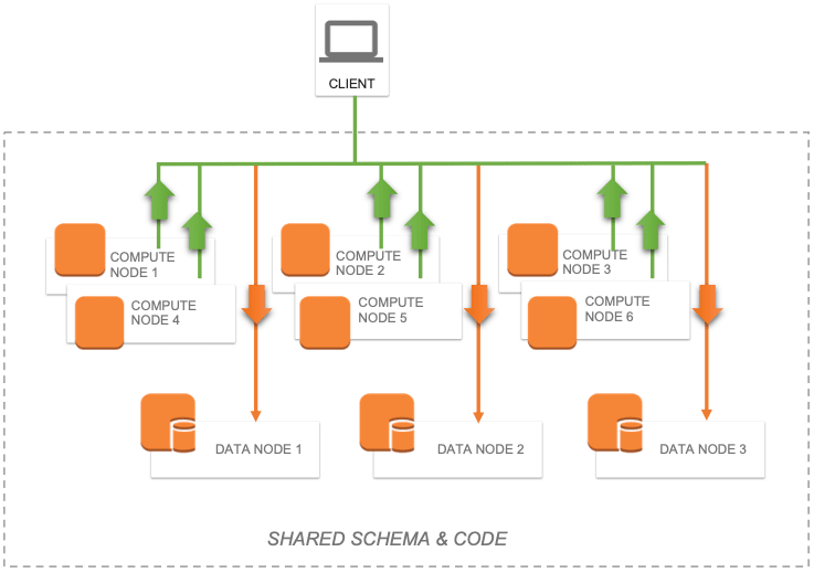
For advanced scenarios where low latencies are required, potentially at odds with a constant influx of data, compute nodes can be added to provide a transparent caching layer for servicing queries.
Compute nodes cache data. Each compute node is associated with a data node for which it caches the corresponding sharded table data and, in addition to that, it also caches non-sharded table data as needed to satisfy queries.
Figure 9.2.2-a: Shard cluster with Compute Nodes
Because compute nodes don’t physically store any data and are meant to support query execution, their hardware profile can be tailored to suit those needs, for example by emphasizing memory and CPU and keeping storage to the bare minimum. Ingestion is forwarded to the data nodes, either directly by the driver (xDBC, Spark) or implicitly by the sharding manager code when “bare” application code runs on a compute node.
Sharded Cluster Illustrations
There are various combinations of deploying a sharded cluster. The following high-level diagrams are provided to illustrate the most common deployment models. These diagrams do not include the networking gateways and details and provide to focus only on the sharded cluster components.
Basic Sharded Cluster
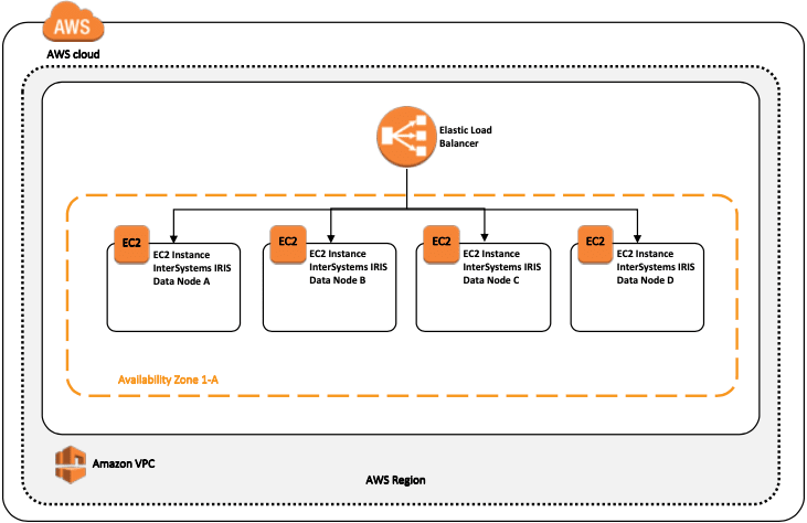
The following diagram is the simplest sharded cluster with four data nodes deployed in a single region and in a single zone. An AWS Elastic Load Balancer (ELB) is used to distribute client connections to any of the sharded cluster nodes
Figure 9.3.1-a: Basic Sharded Cluster
In this basic model, there is no resiliency or high availability provided beyond that of what AWS provides for a single virtual machine and its attached SSD persistent storage. Two separate network interface adapters are recommended to provide both network security isolation for the inbound client connections and also bandwidth isolation between the client traffic and the sharded cluster communications.
Basic Sharded Cluster with High Availability
The following diagram is the simplest sharded cluster with four mirrored data nodes deployed in a single region and splitting each node’s mirror between zones. An AWS Load Balancer is used to distribute client connections to any of the sharded cluster nodes.
High availability is provided through the use of InterSystems database mirroring which will maintain a synchronously replicated mirror in a secondary zone within the region.
Three separate network interface adapters are recommended to provide both network security isolation for the inbound client connections and bandwidth isolation between the client traffic, the sharded cluster communications, and the synchronous mirror traffic between the node pairs.
Figure 9.3.2-a: Basic Sharded Cluster with High Availability

This deployment model also introduces the mirror arbiter as described in an earlier section of this article.
Sharded Cluster with Separate Compute Nodes
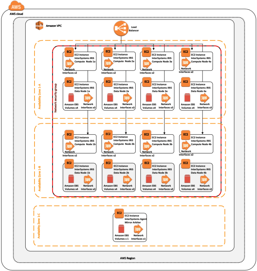
The following diagram expands the sharded cluster for massive user/query concurrency with separate compute nodes and four data nodes. The Cloud Load Balancer server pool only contains the addresses of the compute nodes. Updates and data ingestion will continue to update directly to the data nodes as before to sustain ultra-low latency performance and avoid interference and congestion of resources between query/analytical workloads from real-time data ingestion.
With this model the allocation of resources can be fine-tuned for scaling of compute/query and ingestion independently allowing for optimal resources where needed in a “just-in-time” and maintaining an economical yet simple solution instead of wasting resources unnecessarily just to scale compute or data.
Compute Nodes lend themselves for a very straightforward use of AWS auto scale grouping (aka Autoscaling) to allow for automatic addition or deletion of instances from a managed instance group based on increased or decreased load. Autoscaling works by adding more instances to your instance group when there is more load (upscaling), and deleting instances when the need for instances is lowered (downscaling).
Details of AWS Autoscaling can be found here.
Figure 9.3.3-a: Sharded Cluster with Separate Compute and Data Nodes
Autoscaling helps cloud-based applications gracefully handle increases in traffic and reduces cost when the need for resources is lower. Simply define the policy and the auto-scaler performs automatic scaling based on the measured load.
Backup Operations
There are multiple options available for backup operations. The following three options are viable for your AWS deployment with InterSystems IRIS.
The first two options, detailed below, incorporate a snapshot type procedure which involves suspending database writes to disk prior to creating the snapshot and then resuming updates once the snapshot was successful.
The following high-level steps are taken to create a clean backup using either of the snapshot methods:
- Pause writes to the database via database External Freeze API call.
- Create snapshots of the OS + data disks.
- Resume database writes via External Thaw API call.
- Backup facility archives to backup location
Details of the External Freeze/Thaw APIs can be found here.
Note: Sample scripts for backups are not included in this document, however periodically check for examples posted to the InterSystems Developer Community. www.community.intersystems.com
The third option is InterSystems Online backup. This is an entry-level approach for smaller deployments with a very simple use case and interface. However, as databases increase in size, external backups with snapshot technology are recommended as a best practice with advantages including the backup of external files, faster restore times, and an enterprise-wide view of data and management tools.
Additional steps such as integrity checks can be added on a periodic interval to ensure clean and consistent backup.
The decision points on which option to use depends on the operational requirements and policies of your organization. InterSystems is available to discuss the various options in more detail.
AWS Elastic Block Store (EBS) Snapshot Backup
Backup operations can be achieved using AWS CLI command-line API along with InterSystems ExternalFreeze/Thaw API capabilities. This allows for true 24x7 operational resiliency and assurance of clean regular backups. Details for managing and creating and automation AWS EBS snapshots can be found here.
Logical Volume Manager (LVM) Snapshots
Alternatively, many of the third-party backup tools available on the market can be used by deploying individual backup agents within the VM itself and leveraging file-level backups in conjunction with Logical Volume Manager (LVM) snapshots.
One of the major benefits to this model is having the ability to have file-level restores of either Windows or Linux based VMs. A couple of points to note with this solution, is since AWS and most other IaaS cloud providers do not provide tape media, all backup repositories are disk-based for short term archiving and have the ability to leverage blob or bucket type low cost storage for long-term retention (LTR). It is highly recommended if using this method to use a backup product that supports de-duplication technologies to make the most efficient use of disk-based backup repositories.
Some examples of these backup products with cloud support include but is not limited to: Commvault, EMC Networker, HPE Data Protector, and Veritas Netbackup. InterSystems does not validate or endorses one product over the other.
Online Backup
For small deployments the built-in Online Backup facility is also a viable option as well. This InterSystems database online backup utility backs up data in database files by capturing all blocks in the databases then writes the output to a sequential file. This proprietary backup mechanism is designed to cause no downtime to users of the production system. Details of Online Backup can be found here.
In AWS, after the online backup has finished, the backup output file and all other files in use by the system must be copied to some other storage location outside of that virtual machine instance. Bucket/Object storage is a good designation for this.
There are two option for using an AWS Single Storage Space (S3) bucket.

Posted on September 27, 2020
Join Our Newsletter. No Spam, Only the good stuff.
Sign up to receive the latest update from our blog.
Related
September 27, 2020

